Monday, July 22, 2013

DIY Jewelry Holder for about $10

So my girlfriend had been eyeing these wooden on the wall jewelry holders for a while that a few sites and some people on Etsy sell. She wanted a way to store her "statement" necklaces and pieces so they were easier to see and reach. Rather than allow her to purchase something well made, and reasonably priced, I insisted that she let me make her one from scratch. Here is the process and some basic guidelines should you choose to try this yourself after the jump.

the finished piece mounted to the wall
another view of the finished piece

Saturday, July 20, 2013

Refinishing an old desk

As I had mentioned in a previous post, my girlfriend and I recently got a new apartment together, and we needed some furniture. Being rather handy, I wanted to make or refinish as much of the furniture as possible. My girlfriend needed a desk (shes a teacher), so I refinished my dads old teaching desk for her use. The original desk was about 100 years old and had three different finished piled on top of each-other. It also had brass hardware that had turned black with age. I started by removing all the drawers and repairing any physical damage to the desk and drawers. I made sure they all fit correctly and closed, and any weak spots were re-enforced where necessary. Next a chemical stripper was used to loosen the old finishes and a very time consuming process of sanding, filing and scraping was undertaken to remove everything. Next I primed and painted the desk and drawers white to make the turquoise color my girlfriend selected really pop. I then spray painted a base coat of turquoise color and hand painted a few layers on top of the mausoleum blue lagoon color. Lastly, I sprayed clear lacquer on any area that would see alot of use (the top and drawers) and then coated the entire desk in a layer of clear polyurethane. The handled were soaked in a vinegar and water mixture for a few hours and then hand polished twice with brass-o. Do not ever coat antique brass with a clear coat to preserve the finish; it will destroy the brass.  If enough people care/are interested I will do a full write-up on how to do this.


The original desk; note the blackened hardware and terrible finish

the finished desk!

Adventures in furniture making

So I recently got a new apartment with my girlfriend and decided that we needed some new furniture. Not wanting to spend a fortune on "fancy" store furniture and not wanting to buy cheap crap that falls apart in a few months I decided to build some of my own.

I stumbled onto this fantastic site, The Design Confidential, on which the author drafts up her own plans for lots of commonly available furniture from many stores. The site is organized fantastically, and is very approachable with excellent plans. More importantly, I felt lazy and did not want to break out the router, and non of her plans called for using a router; instead they called for a pocket-hole jig.

For those unfamiliar (that included me until a few weeks ago), the Kreg pocket hole jigs you see used on all these furniture plan sites are not part of some global marketing conspiracy; Kreg really does make one of the only affordable jigs around and it is just the best thing I have bought for woodworking in years. I love it. Buy one; seriously, it makes making furniture so much easier.


Anyways on to the furniture!

Friday, December 28, 2012

Cleaning and repairing my Koolance Exos2 watercooler

     So a while back, I bought a Koolance Exos2 for my old socket 478 Pentium gaming rig. It served me wonderfully for 3 or 4 years, and then like a dummy I ignored Koolance's warnings not add color to the coolant, bought a syringe of color, and added it in. A few months later, I went to add more color and accidently grabbed a syringe of arctic thermal paste and put that in. Stupidly. Well stupidity aside, my system still ran for a while, but recently (about 2 years later) it finally clogged up, and gave up. While I don't use liquid cooling on my current rig, the Exos2 was a great system and it seemed a huge waste to just throw it out, so I decided that I would attempt to clean and repair it.
     I write this not so much as a guide but more of a log of what I did along the way in case this helps anyone who is in a similar situation to me with a clogged/dirty/broken out of warranty liquid cooling system like this one. I encourage anyone with similar stories, or thoughts/tips/tricks to please comment on how you fixed your situation.

Saturday, December 22, 2012

Nerf Stormfire Modding

This is a re-post of my original post over at the wonderful NerfHQ.

If you aren't aware, as part of the new Dart-Tag line up for 2009, Nerf released a package called the Dart Tag Capture the Flag, which has two stormfire pistols in it. They are pretty neat pistols, if a bit large for a pistol, with a fairly sizable plunger tube. This writeup will cover basic modifications to your stormfire pistol.

Mod Details:
-Storm Fire Pistol
-Intended Ammo: Standard Nerf Micro Darts
-Overall Mod Difficulty: medium to beginner

Materials Required:
-Silicon pip tape
-Lubricant of your choosing
-Super glue
-Hot Glue
-1/2" CPVC
-Craft Foam
-#41 Oring
-#52U ace spring


Tools Required:

-Dremel with sanding attachments
-Hacksaw
-Phillips Screwdriver
-Needle Nose Pliars
-Hot Glue gun


Step 1: Dissasemble the pistol, dont forget to remove the set screw for the barrel cap.


Step 2: Once the gun is fully taken apart you should have something that looks like what you see below. If you have ever modded any nerf pistol the internals are fairly simple and should make sense to you. Dont loose any springs


Step 3: We want to remove the barrel and plunger assembly. It should be glued together as one cohesive piece, remove the plunger spring assembly and set that aside  we will work on that later. The barrel assembly needs to be modified to accept 1/2" cpvc. If you look inside you will see the AR, pretty standard. You want to cut the barrel assembly with your hack saw where the barrel for the dart meets the slightly larger orange piece below:

Make sure to sand down the outside of your cut so you have a nice smooth surface.

Step 4: To remove the AR use a drill with a drill bit that will fit through the small hole you can see from the back end of the plunger tube. Making this hole too wide will reduce the effectiveness of the gun. Punch through with the drill bit, it should punch out the remainder of the dart peg on the front. Use your dremel, or pliars and pull out the rest of the ar assembly from the front of the barrel assembly.


Step 5: Now take your dremel and bore/sand out the inside the plunger assembly (the orange bit) until it is wide enough for a piece of 1/2 CPVC to fit inside snugly. You want the CPVC to be able to fit all the way down to the disc with the small hole that you drilled through earlier: 


Step 6: Cut a 2.5" length of your cpvc, make sure it fits down into your sanded out plunger tube first. Put some super glue or adhesive of your choice around the bottom of the cpvc and insert it into the plunger assembly making sure that it is flush with the bottom, and that it is strait. I used hotglue after to seal any loose gaps around the outside of the cvpc:


Step 7: Now we move on to the plunger itself. Unscrew the plunger head, it comes apart into a few pieces. I would not suggest streching the exsisting spring. I kept the exsisting spring and added half of an ace# 52U spring. Re-attach the plunger head. 

Now take your silicone pipe take and wrap approximatly a 16" piece tightly around the orange plunger head. Put the stock oring over this, and then your #41 oring below this oring as a stabilizer. Lastly you will want to put some hot glue on the face of the plunger head, and use this glue to attach a piece of craft foam to the top. Trim down the craft foam once the glue has dried. This will help cushion the much stronger plunger.


Step 8: Lube up your plunger head, and re-insert it into the plunger tube. re-assemble the gun and you are done! Should look like this:


Test fire the gun make sure everything works right.


Ranges for mine with the black foam sonic micros are decent
55 to 60' flat
85+ angled
This was at night on a very VERY humid evening, you could see fog coming out of the barrel due to the compressed humid air. Dryer conditions will yield better results.

I am currently working on a second StormFire with some changes with the barrel assembly to allow for greater accuracy. 

Wednesday, December 19, 2012

Putting and LED bladder indicator in a Nerf Magstrike


I present to you a write-up on how to make and install an L.E.D. magstrike bladder indicator. This can be installed in pretty much any air powered gun, although I think you will run into a bit of a space issue in an RF 20. This is a re-post of my original post from the wonderful Nerf-HQ forums...a place I whole heatedly recommend you visit if you are into foam guns.

Caution!:

This writeup assumes that you have basic soldering skills, and are already capable with using the tools presented here. Soldering irons are very hot, and very dangerous. They can destroy your guns, and your hands. If you dont know what you are doing, please dont attempt to do this. Many types of solders contain dangerous chemicals, sometimes even lead. Dont do this on your mom/spouse/gf's nice kitchen table.

Materials Needed:

-30w or higher soldering iron
-rosin core, lead free solder
-Wirecutters/strippers
-Hot glue gun and glue sticks
-some thin wire, I suggest you get colored wire. Scavenge old electronics for it or rip open old vga cables or something.
-Heatshrink tubing of appropriate size for your wire
-Electrical Tape
-2k ohm resistor
-1 red led (5mm, frosted. used for indicator not light source)
-1 green led (5mm, frosted. used for indicator not light source)
-2 5mm LED holders (Radio Shack Catalog #: 276-079)
-membrane "dome" switch. - I have a ton of parts, not sure where to source these, this is an example from digikey (digikey part: 401-1924-ND)
-Contact switch - these are in EVERY nerf gun with a light that is trigger activated
-Your choice of battery and holder

How To:

    Let me start off by apologizing that I didn't take pictures during the process, i took these after, so some things may not be clear, but you already know how to solder.
The goal here is to have 2 lights that indicate when the bladder is half full, and when the bladder is about 80 percent full. The red led will be for half full, and the green will be for 80 percent. On my magstrike here, once the bladder fills up enough that it pushes against the white retainer plates, it is half full. When the over-pressure valve hits the back of the tank area, it is about 80 percent full. So I will be placing switches in both of these locations:


Your first step is going to be to drill 2 1/4" holes someplace on the shell that you want to put the LED's. I chose to put them on the top of the tank because I was in a rush and didn't feel like doing much thinking. Make sure wherever you place them that you have sufficient room for the internal components.


Once you have made these holes, you need to wire up your switches. The first switch is the dome switch. These are small, nearly flat switches that work when they are pressed. Basically what is inside the keypad on your phone or your keyboard. I drilled a small hole for wires from the switch at the top of the retainer plate that keeps the bladder in place, and then glued the switch to the inside of the retainer plate. I then wrapped a few layers of electrical tape over the switch to make it a bit thicker so that it would definitely be pressed by the bladder, and so that it would not cut the bladder.


When you solder wires to the switch, leave plenty of wire attached, you can cut it and route it later through the blaster. Make sure you heat-shrink around any bare wire contacts so you dont have any shorts or sharp edges.

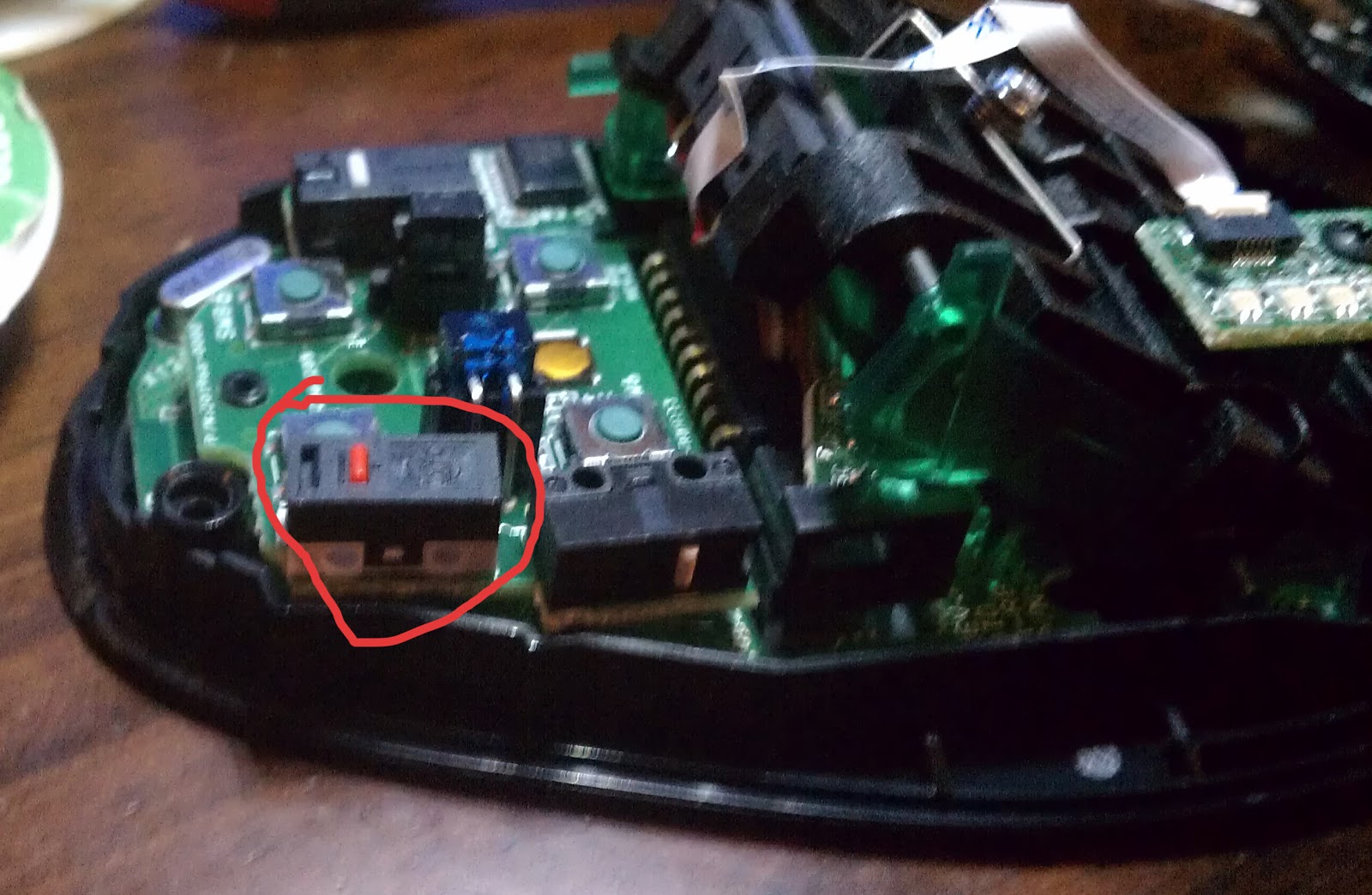
Next you are going to place the rear contact switch. For this I used a switch out of a firefly, the little metal contact one that triggers the flash. Cut a space in the stopper plate in the back of the magstrike that you can fit the switch into, and hot glue it in place so that when the bladder over-pressure valve extends, it will press the switch closed. I also glued a small piece of foam to the side of the over-pressure valve so that it would have no trouble pushing the switch. The size of this foam can be used to calibrate when the switch is pressed.


The next step is to wire up your LED's. I will give some additional tips on LED's at the end of this writeup, so if you have no idea what I am talking about read that part after this. Select the order in which you want to attach your LED's, and place wires for them through the 2 1/4 inch holes you drilled. Solder these wires to the LED's, and make sure you heat-shrink the cathode and annodes of the LEDs. Insert the LED into the holder and push it into the hole, it should snap neatly into place with a tight secure fit.


Lastly you need to place your battery. Because I was in a rush, and used what was availible, I stuck a small inline batter case and a 12v 23amp battery inside the blaster. You can use whatever you want, and place it inside or outside at your pleasure. I will give some additional information about batteries later in this writeup.


Wiring it all up

This is where it can get tricky, and if you dont know anything about electronics I am sorry. I will provide a wiring diagram here, and some basic information about LED's and batteries, but I am not writing up a detailed guide to electronics and wiring. I may be an electrical engineer, but there are plenty of better guides for that on the net already. Check out sparkfun for some great guides and tutorials on soldering, wiring, and electronics if you need more.


The positive end of the battery should be wired to the 2kohm resistor, and then from the resistor should split off and power each of the positive ends of the LED's (the longer legs).
The negative end of the batter should be split to go to each of the 2 switches, and then each switch should be wired to its respective LED's short leg.
Once you are done, you will have a working indicator!

Notes about electronics, LED's and wiring

Some important things here for those of you who dont know. Electricity has 2 basic components, voltage and current. Voltage is like water pressure, its the amount of force the electricity has to move through a circuit. Current is like the volume of the water, its the amount of electrons moving via the voltage that can actually do stuff. What makes things work, bulbs light, motors turn etc is NOT voltage, it is current. This is important to understand. Any device will draw only as much current as it needs, but will be forced to accept whatever voltage it is given. with devices like LED's, this will cause the LED to burn out very quickly. This is why the resistor is VERY IMPORTANT. Each LED only needs about 1.2 volts to light up, and less than 500ma of current. The resistor is very important in making the circuit work and keeping the LED's lit. Do not wire this circuit without a resistor. The value of the resistor can be changed and will alter the brightness of the led's. I selected 2kohms as it makes them bright enough to see, but not too bright to give me away.

Batteries: Ideally you should have about 3 volts to run this circuit correctly, more voltage wont hurt, less voltage wont work very well or at all. You MUST have the resistor wired to the LED's to protect them in the circuit. Something I want to drive home about batteries: they dont work the way you all think they do. Stop using freaking 9volt batteries for everything. All batteries have a voltage indicator, but they also have a current indicator measured in amp hours. That is how many hours they can provide 1 amp of current. 9 volt batteries BARELY produce any current and cant provide it for long. They are for trickle devices like smoke detectors and walkie talkies. NOT FOR RUNNING MOTORS AND LIGHTS. In my gun here, I used a 12 volt batter that supplies 1 amp for 23 hours. If I hooked a stampede up to this battery it would operate for all of 8 seconds. This is because the battery has a very slow discharge rate and would exhaust all the current immediately. However, with something like an LED that sips on the current, it will keep the led's illuminated for days, probably a few weeks.

VERY NON-TECHNICAL DISCLAIMER
(The following is extremely non-engineering speak)

Seriously. Not to go off on a tangent, but I want to yell at everyone some more (our hvz game just ended, I died in the last 10 minutes of the final mission, and im hungry. Sorry for being grumpy). Those of you that keep replacing batteries in vulcans, stampedes and barricades etc with 9volts need to just cut it out. It makes me so stabby and punchy. Look at that massive tray in your stampede. Takes 6 C batteries, about 9 volts. So how is it that if they are that big and 9 volts that you think one small 9volt will replace them all! But seriously to bring this back to relevant information, 9 volt batteries have a very very very low current output which is what gives batteries their "making stuff happen" power. Thats why AAA, AA, C, and D batteries all put out 1.5 volts, but are each larger. The larger batteries have a greater current output and last longer. Okay rant over.

The finished product:


Questions? Comments? Thoughts? Make sure you post your questions here and dont PM me, especially if they are technical, so that others may benefit from your ability to point out the flaws of my writeup!
Enjoy!

Fixing the left click on a Logitech G7


Fixing the sticking button on my Logitech G7.

So I've, had a first edition Logitech G7 for a number of years and what a great mouse. Unfortunately a few years ago the left click button started sticking, and performing a rapid double click within whatever software I was using. This more or less negated my ability to single click on anything; desktop icons were double clicked, web-forms were submitted by accident...etc. It made the mouse unusable. I never got around to fixing the mouse, and set it aside. Today I finally decided to right this wrong and fix my old mouse. I found a great guide on the overclockers forum here, but following that guide I found my leaf spring to be ruined and un-fixable.
    Thus I am now forced to replace the "clicky" switch entirely, and figured there might be some others out there in my situation that could use an example. After taking apart the mouse, (there are four screws on the bottom, one of which requires you to break the warranty sticker, the other three may cause you to damage the non-stick pads...please be careful and proceed at your own risk) and running through the steps in the aforementioned guide, I realized I had to remove and replace the switch.
    My parts area had a huge number of random switches but I did not have the correct three pin 5mm momentary mouse button switch laying around in my parts box, I found an old PS2 mouse, ripped it open and was pleased to find that it had two of the exact switches I was looking for!

The logictech G7 needs 3 pin switches, so make sure your donor mouse has 3 pin switches. You will need a soldering iron, and either copper braided de-solder wick or a solder sucker. I am going to assume you know how to solder and de-solder, if not there are many wonderful guides out there on the internet. Flip the circuit board for the donor mouse over and locate the solder points for one of the switches:

Once you locate the solder pads for one of the switches, remove the switch with your soldering iron and de-soldering tools. Be careful not to overheat the metal on the pins which could cause them to pull out of the plastic switch thus ruining your day (and your mouse).
     Next you will need to de-solder the broken switch from the logitech G7, which is actually pretty tricky due to the way that the circuit board the switch is attached to is located. Here, Ill show you:
As you can see, there are two circuit boards with a small gap in-between them. On the opposite side of the mouse by the right click button there is an 8 pin jumper that connects the two boards. At first, I thought that the jumper might have been a pin and socket setup where I could pull them apart, but alas, it is soldered on. If you are careful, and have a good fine tip soldering iron you can actually de-solder the broken switch without separating the boards. If you do not have those skills however, you will have to de-solder the jumper in order to separate the boards. 
   Assuming that you can access the switch without taking the boards apart, you will need to de-solder three pins on the Logitech G7 board:
Once removed, the board should be clean and the holes should be clean and free of solder. Make sure no traces were cut or lifted off the board. Once again, if you dont know how to de-solder you may want to ask a friend for help so that you dont ruin your G7.
Assuming you reached this step with me, take your donor switch you removed from a donor mouse earlier and place it into the holes in the G7 circuit board, and verify that it fits flush against the circuit board. If the switch does not fit flush, do not force it. Find a switch that will fit flush. You should also check that the "clicky" button on the new switch matches the same location as the old switch. Hold it up against the right click button to verify this, or the G7 will not work properly. Once you have verified that the switch is a match and fits, solder it back into place:
At this point is a decent idea to throw the battery back into the mouse and just verify that your soldering job did the trick and the computer will register the left mouse clicks. If everything is working correctly, pull the battery out, and put your mouse back together! You now have hopefully another few years of use out of your G7.
Please feel free to ask questions or leave suggestions if you perform this same surgery on your G7 or similar mouse.